David's RV-10 Build

Just another RV-10 builders log

Category: Empennage

HS Front Spar, Ribs, & Skins

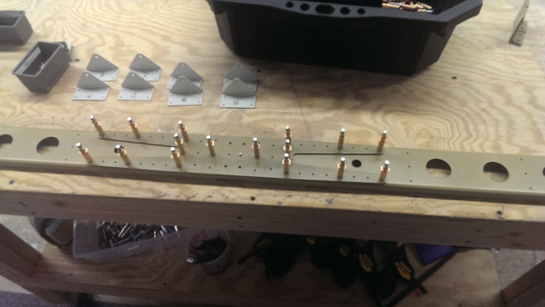
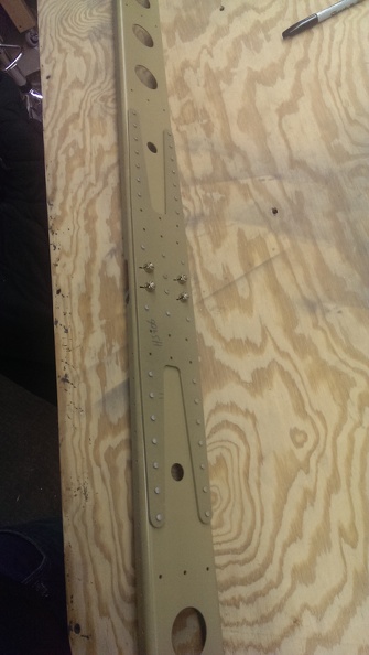
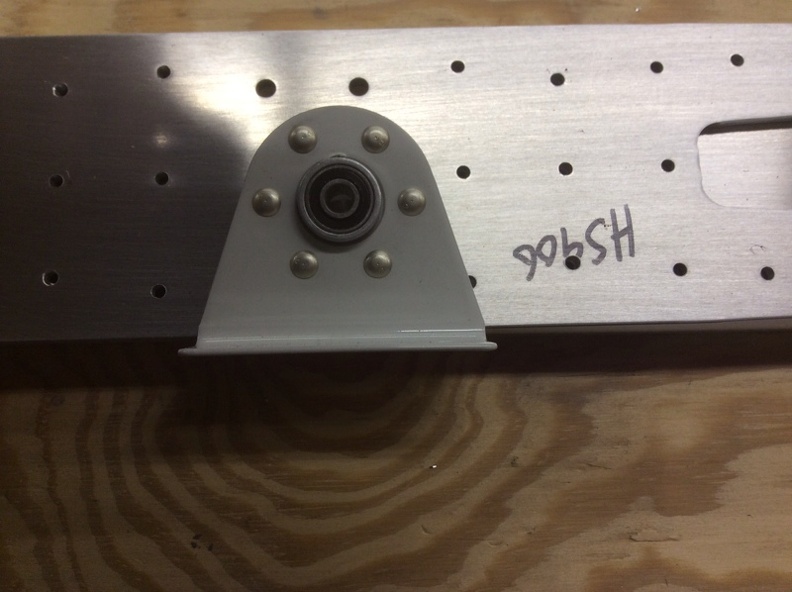
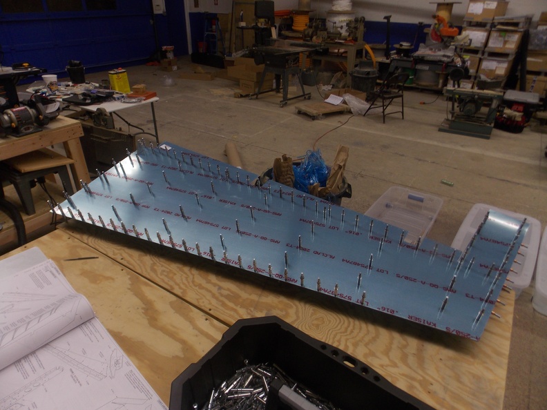
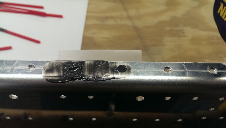
On Friday I called Van’s and spoke with tech support. After describing the issue, I was advised that a -4 rivet could be put in place instead. When I asked about the -4 still being too deep, We reviewed the plan’s again and determined that since all it was holding was the stiffner, Which is riveted closely on both sides, as well as the vertical portion. I could “patch” the hole with JB Weld and redrill it. This is NOT recommend for key places. I apparently got really lucky and it would not be an issue.

I took some tape and created a seal so the JB Weld would not drop through and be smooth. I also filled in a 2nd rivet that was just a LITTLE deep, not bad at all. I smoothed it out as best I could, the rest will need to be sanded down a bit.

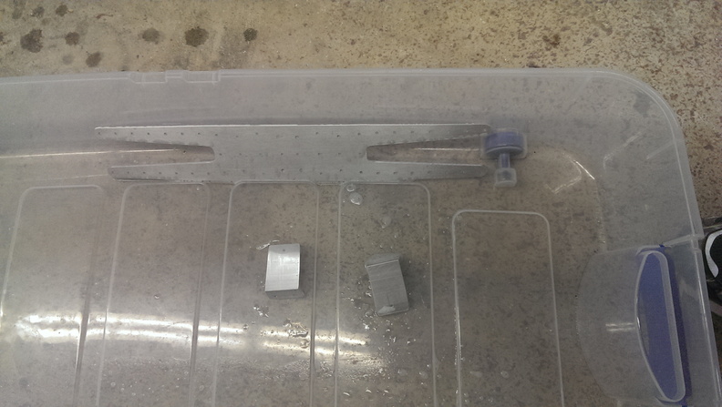
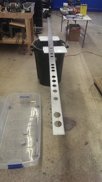
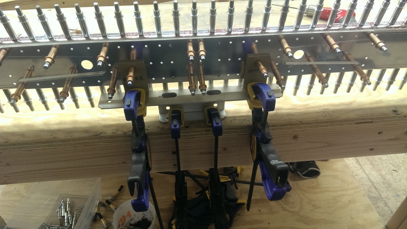
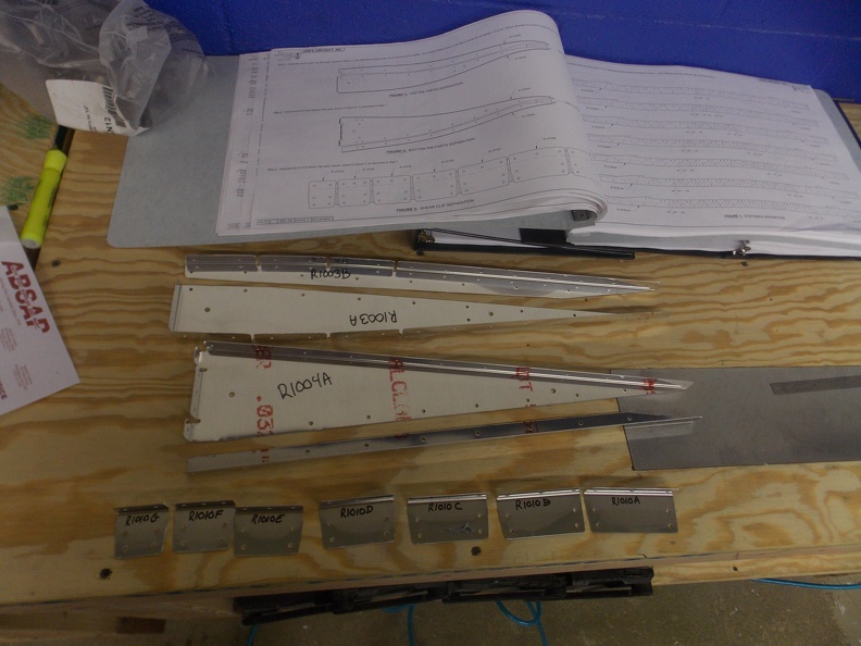
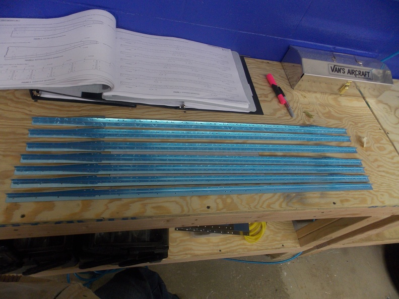
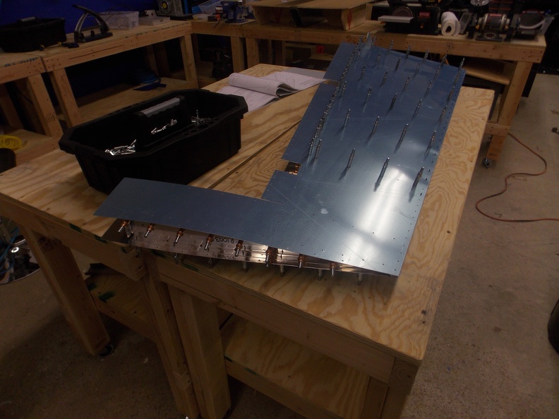
While waiting for this to dry I went on to the next set of parts that I could work on. The plans have you modify 4 HS-1004 ribs. This was pretty easy. Just cut some minor sections out as well as bending 2 of them. Next I grabbed the HS-905 ribs and began deburring them. This is the first section of the plans that really confused me. The parts they send you do not look like the parts in the plans. Van’s has apparently added lightening holes to each of the nose ribs and you no longer need to cut the oval as described in the plans. After painfully removing the blue plastic from everything, I deburred the edges of all the ribs that I had worked on so far.

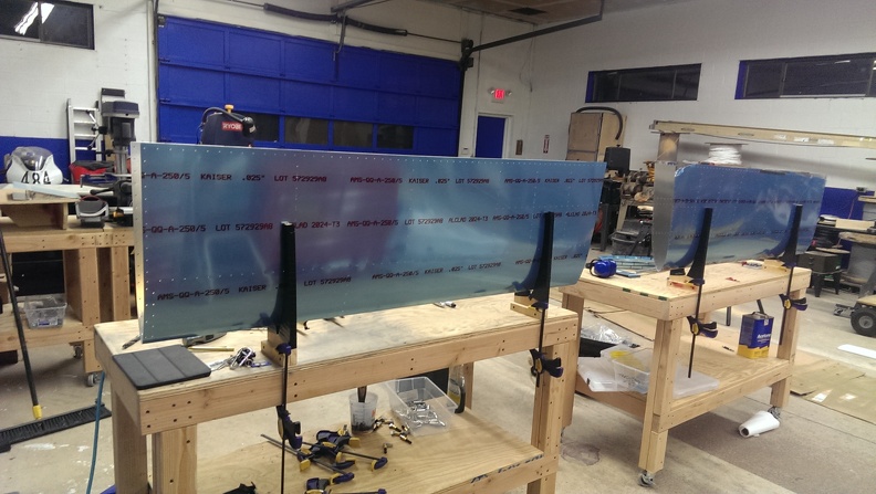
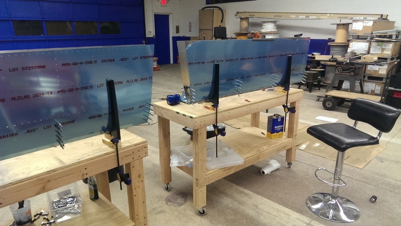
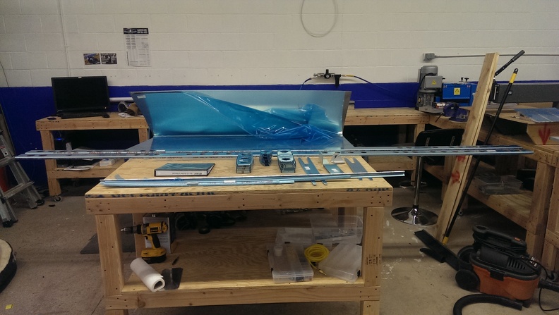
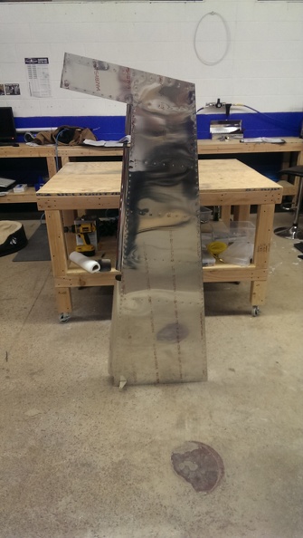
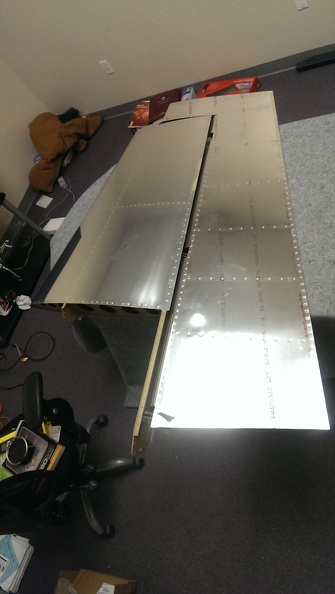
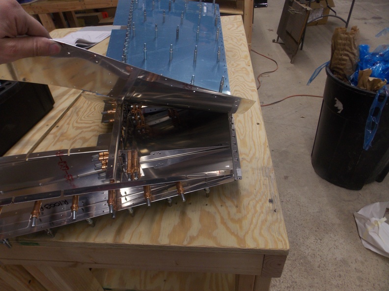
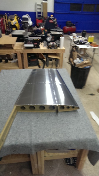
Next I fabricated 4 cradle stands and wrapped them in black vinyl electrical tape to protect the skins. Finally I skipped ahead of the plans and cleco’d the nose ribs in. Looks like I will be taking these out when it is time to work on the spar again.

HS Continued

Today I began by cleaning & priming the components I made so far. The process is relatively simple. Wash with Dawn soap. I use one of those handle/sponge things you can get anywhere. Next I rinse it in a bucket of fresh water. Next I take a small container filled with POR-15 Metal Ready and brush it on to every exposed surface of material. After letting it sit for 30 minutes I dump the pieces into the last fresh water tank. Next, I will sit the pieces out to dry. If parts are exceptionally damp I will hit them with a towel to absorb as much moisture as possible. Once that is done, I’ll spray it with SEM EzCoat Primer. As I’ve said before, this stuff dries incredibly fast! I’ve literally watched it dry before my eyes.

Part’s coated in acid waiting to be washed

Parts waiting to be primed

Parts  Primed, Ready to Rivet

The rear spar riveted and “complete” for this step

Since I had plenty of time let, I decided to continue on to the next step that I could do.

Next I had to cut and deburr the HS-1013, HS-1014, & HS-1015 stiffners. This was long and boring but had to be done. Next the plans have you mark a 1/4″ line on the 2 HS-1013 stiffners and line them up with the 33rd hole from the edge of the spar & clamp them in place. Next you begin the process of match drilling. Once complete, the HS-1007 Spar doubler gets added as well as the HS-1008 attachment plates. It took me a little while but I found a old mounting bracket for some Andrews Diplexer’s ( I doubt anyone will find one of these ) to hold the entire assembly to the table. Once everything was locked down I did some more match drilling.

While countersinking the 9 center holes on the top half, I had not noticed the microstop counter sink got jammed and the “gate” was set far deeper than I wanted. When I was countersinking the first hole it popped free, and was a relatively deep counter sink. I will ask van’s about it in the morning.

Horizontal Stabilizer start!

Today I started by gathering all the parts for the horizontal stabilizer. This is where things really start to get big. I can also tell that this area clearly gets hit with a lot of force as everything is far thicker than everything else I’ve put together. The spar’s clock in at just over 11′ long!


I really didn’t take many pictures in order as I have been trying to do. First I took off the plastic on the HS1003 Rear Spar & the HS906 Rear Spar Doubler. Next I cleco’d it together, and began to match drill all the holes per the plans. After counter sinking the 2 holes in the center and deburing every hole, I began match drilling the hing brackets. After that was done I deburred the edges (Step 1) and scruffed the pieces for primer.

Since I had no desire to prime today, I continued ahead with the plans. The next thing was the flange bearing. This was incredibly easy to do and I spent more time grabbing tools then I did working on the piece.

Since I couldn’t attach the flange bearing to the rear spar, I skipped another step. Steps 3 & 4 on pg 8-3 are essentially the same. You make the same piece (HS1008 Front Spar Attach Bracket) but they are opposite sides. I think the amount of time I saved on the flange bearing went into in these 2 pieces. You take a 6″ long x 2. 1/2″ tall x 2″ deep angle aluminum and cut it down every which way possible. This really wasn’t difficult compared to some of the things I used to machine years ago. But still time consuming.

Everything waiting to get primed for now

Rudder Complete!

After letting the rudder sit for the last week, I started to complete the rudder. I first started by running a test piece on on the practice kit. After feeling pretty good about the results I popped out all the clecos and installed all the rivets and held them on with some rivet tape.

Next I started working on the counterweights. I did mess up here by putting the crease in without the weight (doh). I do believe I did a good job fixing the crease. Getting the counter weight on was relatively easy. Next I backed up a few steps and rolled the leading edge of the rudder. This was a gigantic pain in the ass. To be honest its the only section that I think looks terrible. But luckily its hidden by the Vertical Stabilizer. After that I pulled off the blue plastic and pretty much called it a night

Proseal The Trailing Edge

Today I began a step that I wasn’t quite interested in doing. Vans has you use an epoxy to secure the trailing edge. This is because during the riveting process you really can’t have any clecos. As I’ve read in the past this is some nasty stuff. After I bought the mini-tube, I discovered that I will be using it again, So in attempt to save the rest. I bought a mixing cup and used about half of it. Next  I verified alignment of the trailing edge and began applying a thin layer of proseal on it. Once I had proseal everywhere (literally everywhere, its so easy to make a mess with this stuff). I laid the second skin on top of it and began clecoing it. I went ahead of the plans here and installed the skeleton next. After installing the skeleton I left it to dry for a few days


Rudder Skins

Today I riveted the stiffeners to the skins. This was a relatively easy task to do. The R1003 ribs were pretty easy as well. The R1004 ribs is where it got a bit tricky. I was able to squeeze all but the last 2 rivets near the trailing edge. I ended up bucking the 2nd to last. After trying several various methods (including indirect back riveting) I elected to use a pop rivet that is called out for the other side. At least they will match now.  I also installed the shear plates (which I forgot to take pictures of). I decided to stop here as the plans call for the use of proseal and I didn’t have the time to commit to the next few steps.


Dimpling & Priming

Today I began the fun process of dimpling and priming. There must be more holes in the rudder skins than the entire vertical stabilizer combined. I’m sure ill say that about something else later. The cleaning process was the same, soap, rinse, acid, rinse. I let the acid sit for 35 minutes. Once I was able to make sure the parts were all dry I grabbed a can of SEM EZCoat. This stuff is the bee’s knees (yeah I went there). I swear it dries the second it is applied to the part. I still give it about a half hour to dry prior to flipping it over and doing the backsides. I fully intended to stop here, but I couldn’t I stop. I decided to rivet a few small pieces. So now I’ve riveted the R1004s to the rudder horn, the spar stiffners, as well as the nut plates. I stopped there as I wanted to make sure the skins dried over night as they were the last pieces I primed.

Dimpled, Ready to prime

Parts primed

Riveted parts

More match drilling

Today I received my stiffner I ordered from Vans. They were nice enough to cut it in half so it would save on shipping. Not too much to talk about today. Just finished making the stiffner, match drilling and taking everything apart.


Rudder Start

Today I started the rudder construction. After gathering every piece for this section, I began by separating the R1003 & R1004 Ribs, & the R1010 Shear Clips. After smoothing all the edges I began on the R1015 Stiffners. Now whenever I have to cut something, I follow the age old adage “Measure Twice, Cut Once”. However, this rule doesn’t work as its intended, when you measure from the wrong spot. I ended up cutting the R1015G-R Stiffner too short by about 2 inches. I’ll end up getting a new one ordered tomorrow.


Next I began cleco’ing the R1004A&B ribs together and match drilling them. This was followed by attaching it to the R1005 Rudder horn. After adding a additional clamp, I matched drilled the 6 holes in horn. Next I attached this assembly to the R1002 Rudder Spar.


Next I began assembling all of the Stiffner/Shear plates assemblies. Once they were all built (minus the one I messed up) I matched drilled all the common holes. Next the directions have you attached them to the Rudder Spar as well as some re-enforcement plates. This is of course followed by match drilling. I also attached the R1012 Counter balance rib. This whole assembly is huge! It is almost as tall as I am. I forgot to take a picture of it.


Next I took a peice of VA-140 and cleco’d it to a Rudder skin. After marking what stuck out, I cut it off and sanded it down to fit inside the skin. Next I attached the skeleton to the other skin, flipped it over, and attached the skin with the trailing edge on it. Since I still have to finish a part, I left a portion uncleco’d so I could have easy access to the area I need to get into.


I am pretty much at a stand still till I get the new part in. I really don’t want to start match drilling the skins with out it.

Vertical Stabilizer Complete!

Promptly at 9:30 the nice fedex lady dropped off my new VS Rear Spar and some other parts. I promptly went to work and started cleco’ing and match drilling. After deburring, counter sinking, and dimpling, I washed the parts with soap, set them in acid for 30 minutes, and primed them. What I like about SEM EZ Coat is that is practically dry to the touch within 30 seconds of applying.While waiting for the acid to set, and the primer to dry. Corey & I worked about riveting some of the internal hard to get to rivets on the skin. (This is a bit out of order, but we had time to kill). Once we completed the forward spar, Corey had to go home. About this time I had determined the primer had dried long enough and began to process it back together. Its amazing how much nicer it looks the 2nd time around.


Once I had this completed I began to attach it the skeleton. Once I made sure everything would line up, I used my offset rivet  set and buck’d them into place. Then I proceeded to finish riveting the skins to the skeleton. This went relatively smoothly all though i had to drill out a few rivets here and there. I grabbed a moving blanket from one of the many I acquired when renting a uhaul trailer earlier this year to prepare to protect my newly minted airplane piece. Next I took off the blue plastic. I have no desire to let this stuff sit on here and become semi-permastuck.


And the obligatory selfie to prove that yes I indeed build this part

David's RV-10 Build © 2015